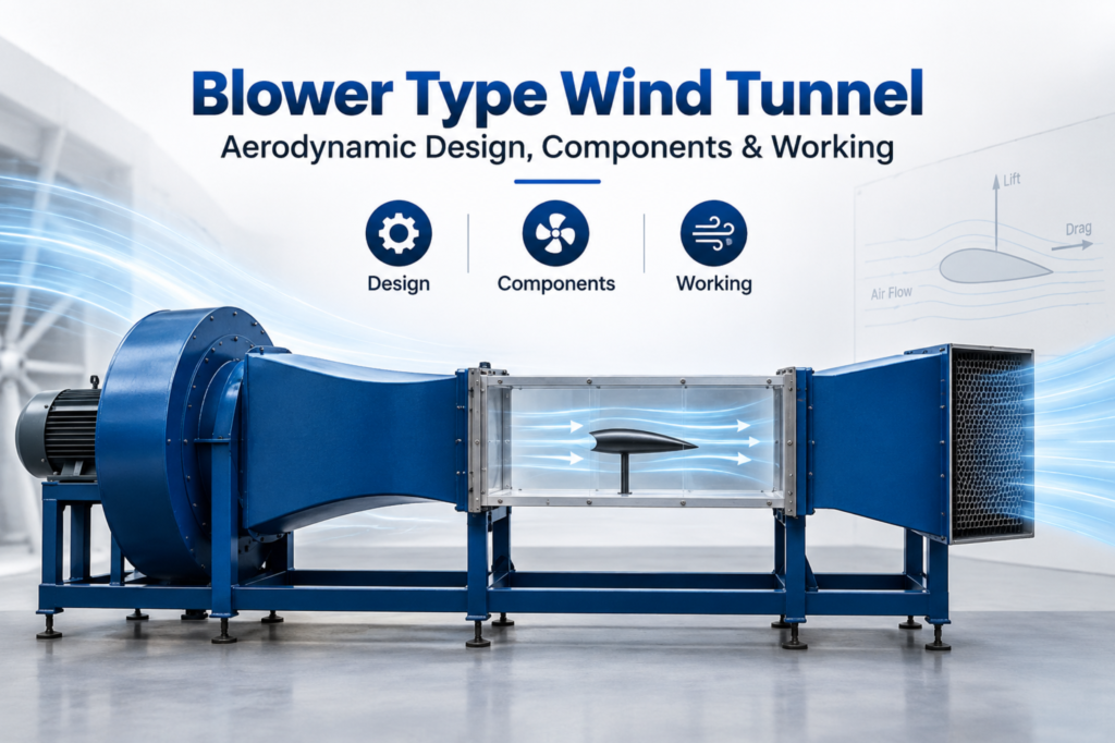





A blower type wind tunnel is one of the most widely used configurations in aerodynamic testing, valued for its simplicity, cost-efficiency, and ability to generate stable, controllable airflow. Unlike suction-based tunnels that pull air through the test section, a blower wind tunnel pushes air from the source end, giving engineers a practical setup for both academic research and industrial testing.
This guide breaks down the core aspects of blower type wind tunnel design, explains the blower type wind tunnel working principle, and walks through the key components that make this configuration effective for aerodynamic and fluid flow studies.
Read more Blog : Shot Blasting Machine Manufacturers in India: Compare Features, Prices & Applications
What Is a Blower Type Wind Tunnel?
A blower wind tunnel positions the fan or blower unit at the upstream end of the tunnel, ahead of the test section. Air is drawn in, pressurized by the blower, and then pushed through the tunnel toward the test model. This setup contrasts with suction-type tunnels, where the fan is placed downstream and draws air through the system instead.
Because the air is actively pushed rather than pulled, this configuration tends to produce a more turbulent airstream at the entry point — which is why careful attention to duct design, flow straightening, and diffuser placement is essential to achieving clean, usable test conditions.
Blower Type Wind Tunnel Design: Key Considerations
1. Blower Selection and Placement
The blower’s capacity, pressure rating, and placement directly determine the velocity range and stability of the airflow. Centrifugal or axial blowers are typically chosen based on the required flow rate and the tunnel’s overall size.
2. Settling Chamber and Flow Straighteners
Since air entering from a blower tends to carry turbulence and swirl, a settling chamber fitted with honeycomb structures or wire mesh screens is used to straighten the flow before it reaches the contraction section.
3. Contraction Cone
The contraction section accelerates the airflow while further reducing turbulence, increasing velocity uniformity as air moves toward the test section. A well-designed contraction ratio is critical to achieving consistent test conditions.
4. Test Section
This is where the actual model or specimen is placed for observation. Its cross-section and length are designed based on the intended application — automotive testing, aerospace research, or educational demonstration.
5 Things to Consider Before Buying a Shot Blasting Machine
Affordable Sand Blasting Machines for Small-Scale Industries
Top Sand Blasting Suppliers in Rajasthan for 2025
5. Diffuser Section
Positioned after the test section, the diffuser gradually expands the airflow, reducing velocity and recovering pressure before the air exits or is recirculated.
Blower Type Wind Tunnel Working Principle
The blower type wind tunnel working principle is fairly straightforward in concept, even though achieving smooth flow in practice requires precise engineering. Air is drawn into the blower, pressurized, and pushed through the settling chamber, where turbulence is reduced. It then passes through the contraction cone, accelerating and stabilizing before entering the test section at a controlled, uniform velocity. After passing the model under test, the air moves through the diffuser, where velocity decreases and pressure is recovered, before the air is either expelled or recirculated depending on whether the tunnel is an open-circuit or closed-circuit design.
This push-based airflow makes blower tunnels particularly well-suited for lower to moderate speed testing, where cost-effectiveness and mechanical simplicity are prioritized over the ultra-high flow uniformity typically required in large-scale aerospace facilities.
Blower Wind Tunnel vs. Suction Wind Tunnel: Quick Comparison
| Feature | Blower Type Wind Tunnel | Suction Type Wind Tunnel |
| Fan Position | Upstream (before test section) | Downstream (after test section) |
| Airflow Method | Air is pushed into the tunnel | Air is pulled through the tunnel |
| Turbulence at Entry | Higher, needs flow straightening | Lower, since air enters through a smooth inlet |
| Common Use Case | General-purpose, educational, industrial testing | Precision aerodynamic research |
| Cost & Complexity | Generally lower cost, simpler build | Often more complex and costly |
Common Applications of Blower Type Wind Tunnels
Blower wind tunnels are widely used across:
- Educational and research labs for teaching fundamental aerodynamic concepts
- Automotive testing for basic drag and airflow visualization studies
- HVAC and ventilation research where airflow behavior needs controlled simulation
- Small-scale industrial testing where budget and space constraints make simpler tunnel designs more practical
Advantages of a Well-Designed Blower Type Wind Tunnel
- Lower construction and operating cost compared to large suction-based facilities
- Simplified mechanical layout, since the blower and motor assembly are easier to access and maintain
- Flexible scaling — blower tunnels can be built at both small lab-bench sizes and larger industrial scales
- Reasonably good flow quality when paired with proper settling chambers and contraction sections
Final Thoughts
A well-engineered blower type wind tunnel offers a practical, cost-efficient way to study airflow behavior, provided the design accounts for the turbulence introduced by an upstream fan. Careful attention to the settling chamber, contraction cone, and diffuser design is what ultimately determines whether the tunnel delivers reliable, repeatable test conditions. For labs, educational institutions, and industries looking for an efficient wind tunnel setup, the blower configuration remains one of the most accessible and adaptable options in aerodynamic testing.